Calculations for the Power Minder
Rec 02-feb-2008 19:08
Regular readers to this blog already know I've been designing a device
to log power failure times and durations, along with a few parameters
such as voltage and frequency. If you're new around here, first read
the post about the
initial concept and requirements,
the isolated serial level converter I designed
for this project and the
MCU selection and pin assignments.
Today is time to think about how we will perform the measurements. There are
actually two sets of measurements: the ones actually used to detect glitches
in the mains power supply and the ones used for showing human-readable
voltage/frequency values. Let's start by the latter, despite the fact
it is more complicated than the former.
While reading this post, you may want to refer to
the Excel worksheet
I used to make all these calculations and the graphs below.
First and foremost, I decided to use a 8MHz crystal as clock source because
I intuitively think it will give us speed to spare and I happened to have
one in my junk box that reads 8.000000. I doubt it is as accurate as the
number of decimal digits suggests, but, what the heck, let's give it a try.
Setting the UART divisor registers to 51, we get 9,615 bps, which is a
negligible 0.2% away from the standard 9,600 bps, so we can expect to have
pretty reliable and uncomplicated serial communications.
The original design of the signal conditioning unit (SCU) combined with
the 220V-6V transformer resulted in what I consider a minor flaw: we
wouldn't be able to run the device on 110V -- at that voltage,
the transformer's secondary winding would produce only 3V, and we need at
least 5.6V for the voltage regulator. We could put a 110-220V voltage
selection switch, but that would be annoying -- we would probably have
to recalibrate the device after changing operating voltage and it would
make a potential source for user error.
So I decided to use a 220V-12V transformer, so our device becomes
"auto-volt". In fact, then operating under 220V, it will throw 17VDC
at the voltage regulator, which will take care of stepping it down to 5V.
Since we plan to keep around 10mA, my guess is that we will have no
problems with the regulator getting too hot. When running under 110V,
we will have about 8.5V at the regulator input, well above the minimum
5.6V needed to maintain regulation. A potential problem is that this
is below the 9V the batteries will supply, so a simple diode will just
not do. Note to myself: design a transistor-based switch with a
specified voltage threshold.
Another consequence is that we need to increase the value
of R1 in the SCU to keep peak voltages going to the ADC and ICP pins
of the AVR below 5V. I raised R1 to 33k, meaning a mains voltage of
220Vrms should make a peak of at most 3.95V after the SCU. At the
maximum votlage of 5V, the device accepts a mains input of at most
278Vrms (about 26% overvoltage). If we get more than that, the built-in
protection diodes at the AVR pins and the 5V1 the zener at the SCU will
handle quick transients well enough to prevent frying the MCU -- or so I hope.
Now, the figure below shows the AC waveform after the SCU -- that is,
after full-wave rectification by the diode bridge and after the voltage
divider resistors:
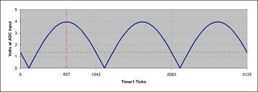
First, setting the Timer1 prescaler to 64, the Timer1 clock will be 8MHz/64=125KHz.
As the picture shows, this means each three semicycles will be exactly 3125 Timer1 ticks
and each semicycle will be 1041.666... Timer1 ticks -- assuming an exact 60Hz mains
frequency.
Measuring the frequency will be rather easy using Timer1's Input Capture (ICP) feature.
Remember, the ICP pin (all digital input pins, actually) have
Schmitt triggers,
so whenever the voltage falls below its lower threshold, we get a high-to-low transition.
Configuring the Input Capture Edge Select bit to detect these high-to-low transitions and enabling
the input capture interrupt, we get called every time a semicycle happens. Or, actually, a bit before --
the "Electrical Characteristics" appendix on the ATmega8's datasheet says the threshold is about
1.35V. Anyway, on each interrupt we accumulate the current value of the Input Capture Register
-- that's the nice feature of the AVR Input Capture system: the value of the Timer1 counter is
copied to the ICR register in the same cycle the level transition is detected, allowing extremely
accurate measurements without worrying about interrupt latencies (how many cycles the CPU
spends jumping to the interrupt vector, saving context and everything before it actually
reaches our code). After doing that for 120 semicycles, we could compute the frequency
f = 60 * 125,000 / accumulator.
Since the Timer1 clock runs at a speed higher than 10
5 Hz, we could in theory
have a precision of five decimal places, or three digits after the decimal point.
As the accuracy of this measurement depends only on the accuracy and stability of the
crystal (and typical stabilities for crystals are about 100ppm), I expect the frequency
measurement of our power minder to be accurate to better than two decimal places after
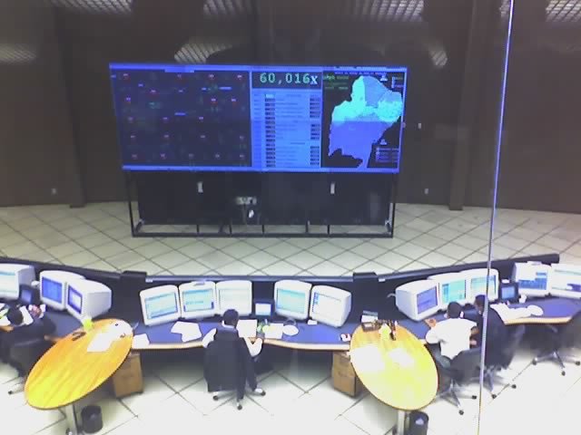
the decimal point. I guess it will most of the time match the value displayed on
ONS's
(the agency that controls the Brazilian electrical power grid) control center shown
below (the "60,016" in the gigantic display -- remember, in Brazil the comma stands
for the decimal point):
What we are actually computing here is the average frequency each 120 semicycles; we
are not computing the frequency
every semicycle because we don't need it that fast.
Even that is mostly just for display purposes.
But life isn't so simple. We must try to avoid
floating point -- it's slow and
increases the code size a lot. So we rewrite our formula as f = 60,000 * 125,000 / accumulator,
with the "60,000" standing for 60 with three decimal places to the left.
But 60,000 * 125,000 turns out to be 7,500,000,000, which fits in 33 bits but not 32.
GCC does support 64-bit arithmetic even in the AVR, but seems like overkill to me.
So what we're gonna do is this: we divide the accumulator by 2 and the compute
f = 3,750,000,000/accumulator. We lose a bit of precision, but makes life very simple.
The bad news is that we can't escape needing a 32-bit division routine -- division takes
several hundred CPU cycles to accomplish. The good news is that GCC does it on the fly
for us, so we don't need to bother that much.
Measuring the voltage is an entirely different matter. There are several possible approaches;
I've elected to implement the simplest first and maybe a more sophisticated one later.
The simplest strategy is what Jerry Whitaker, in Chapter 10 of his
"
AC Power Systems Handbook"
would call a "peak responding, RMS calibrated" meter. Now, because of the accurate timing,
we know with quite high precision where the wave peak will be: the vertical red line
in the graph above shows it will happen around Timer1 tick 637. So we arm the ADC a few
cycles in advance so that its sample-and-hold happens precisely at that moment.
This brings us the peak voltage. We accumulate this for 120 semicycles then scale it
properly to give us a result directly in Volts-RMS.
In the accompanying Excel worksheet you can follow the conversion factor calculation,
taking into account the transformer windings, values of the voltage divider resistors,
ADC voltage reference and maximum values, accumulation and the peak-to-RMS conversion
factor. It also tackles the need to use integer-only arithmetic. In the end, it gets
pretty simple: we multiply the 16-bit accumulator by 2798. We then discard the lower
16 bits; the upper 16 bits will be the RMS voltage (x10), so we get the voltage reading
with one decimal place.
Strictly from the math, this decimal place may be justifiable: 220V/1024 ADC steps
is ~0.2, but the AVR ADC is rather noisy in the two least significant digits. On the
other hand, we are averaging 120 measurements, so this should improve our apparent
resolution by on the order of sqrt(120) or a about a factor of 11. Despite this
apparent precision, way too many things contribute for inaccuracy -- the resistors
in the SCU are accurate only to 1% and who knows about the transformer windings.
Because of all that, I will be more than happy if the measurements turn out to be
within +/- 5V of the correct value. It will be more than enough for the device's primary
purpose of monitoring power failures.
The sophisticated way would be to compute the true RMS voltage: we'd need to sample
several points during each semicycle, square the values (10x10 bit multiplications!),
accumulate them and compute a square root at the end. That's a lot of computation
that will certainly complicate timing issues. However, it would be kinda cool: the
device would give correct results even for non-sinusoidal waveforms.
But for now let's keep it simple. The mere act of integrating all the subsystems
and getting them to work together is enough fun for now. "Put it work first, improve
it later", said the wise man.
Now I'm convinced I have a reasonably decent plan. The next step would be to draw
the final schematics, but I'm eager to test all this, so I'll start assembly
right away and document everything later. Stay tuned.
Follow-ups:
top
