Kiko
| You are here: Kiko > EmbeddedSystems > SimpleTimerCounter2313 | Printable | topic end |
Start of topic | Skip to actions
version does not have the output connectors. 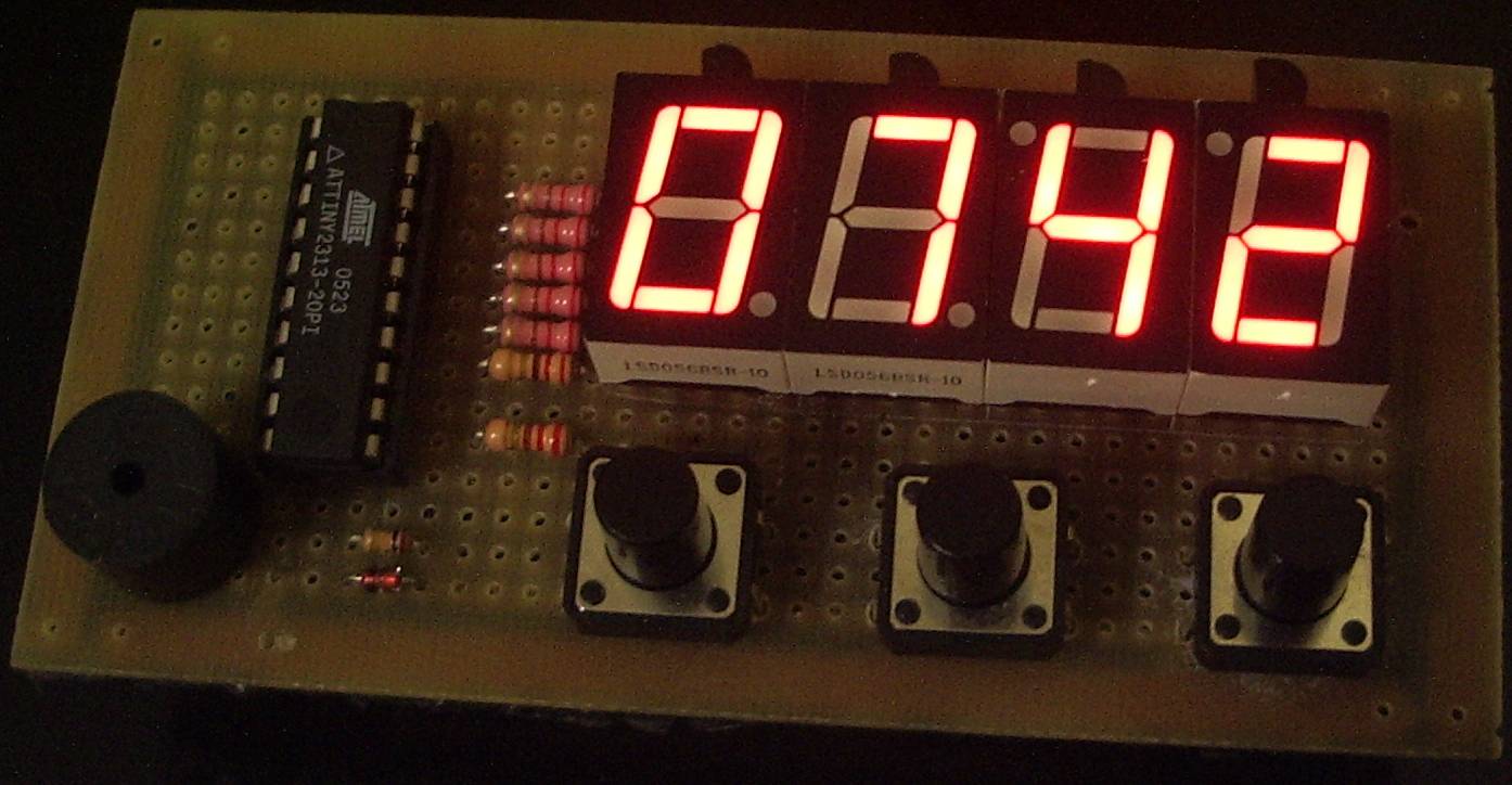
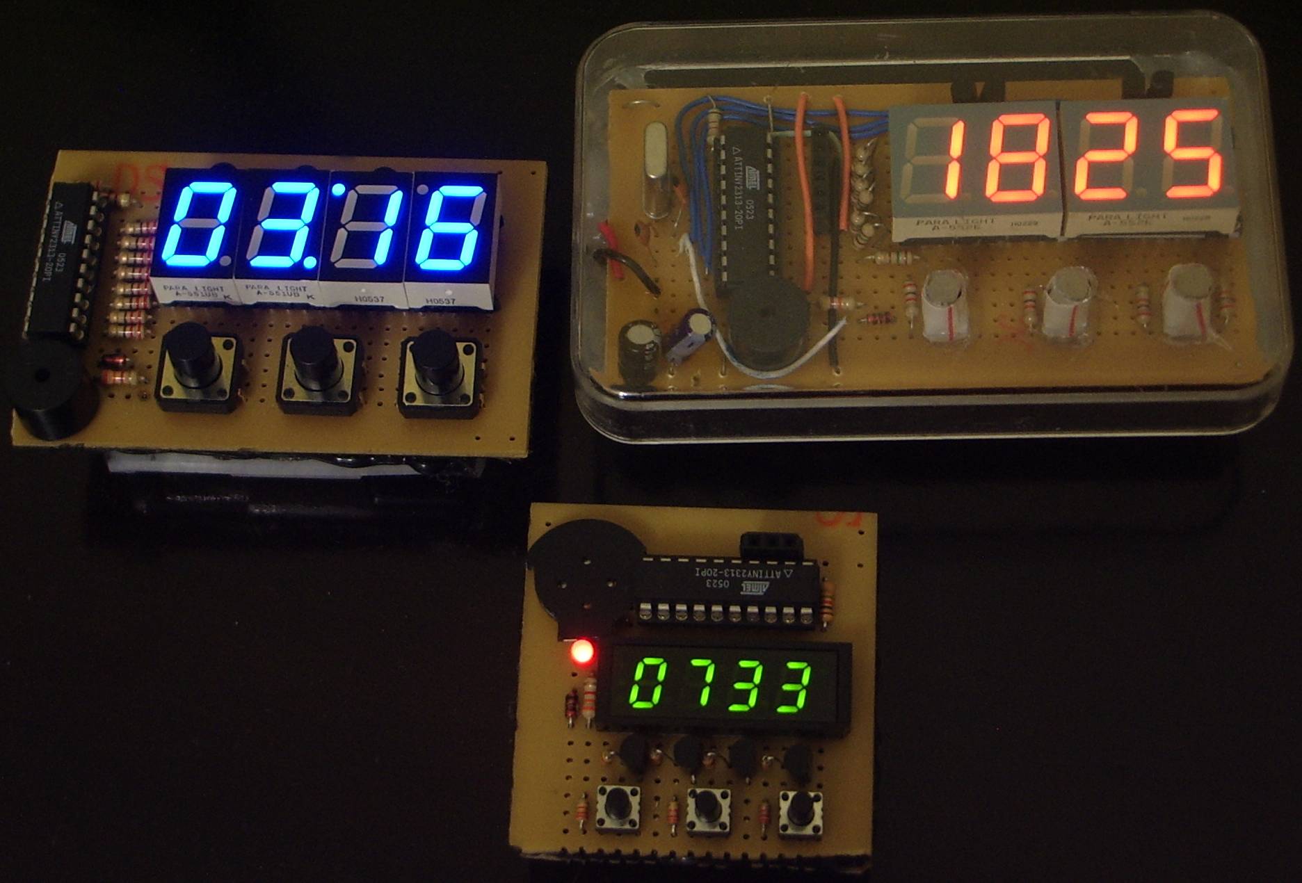
different displays |
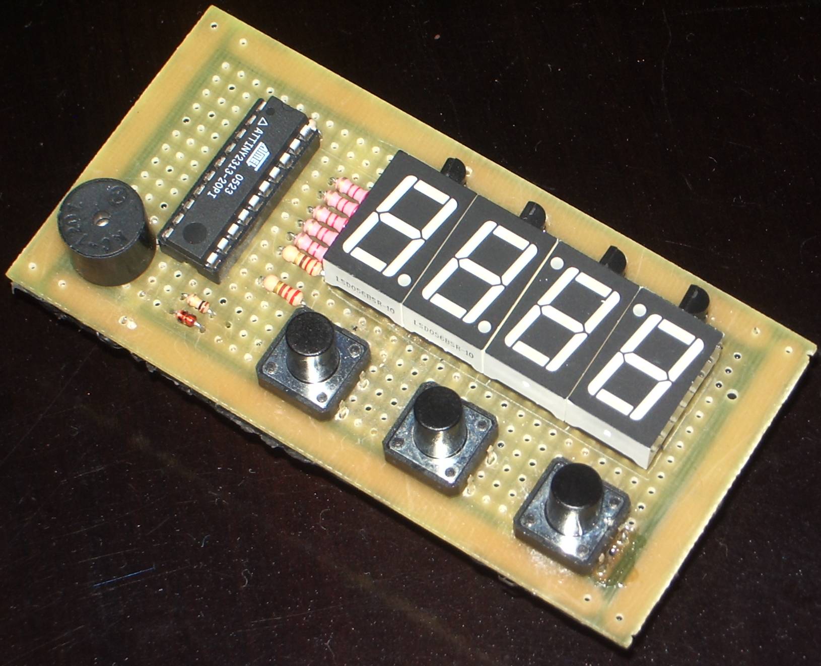
ATtiny2313-based Simple Timer/Counter
KTimer is a simple ATtiny2313-based battery-powered timer/counter which beeps after a specified period much like microwave oven ones. It can control an external device and can also operate as a chronometer or hand counter.Warning
Bringing a homemade timer in your luggage may get you into complications with airport security.Hardware Features
- Handheld size, 8.5 x 4.5 cm
- Powered from 3 AA alkaline batteries
- Battery life: ~4 years in standby mode, >80 hours in active mode
- 4-digit 7-segment display in multiplexed mode for maximum brightness
- 3 key keypad
- Buzzer with frequency synthetizer
- Connector with signals for external power stage allowing control of other devices
- Connector with 5V-level serial port for communications
- Crystal-less circuit
- Low cost, less than US$ 15 in materials
Firmware Features
- Countdown timer beeps for 30 seconds when timeout expires
- Extremely simple operation, just like microwave oven timers
- Two buttons set up the time, incrementing or decrementing in one minute steps
- Another button starts/stops the countdown
- 99 minute maximum countdown period
- Upcounting chronometer
- Hand counter, upcounts on keypress
- Auto-shutdown after 20 seconds of inactivity
- AVR910-compatible bootloader allows in-system firmware upgrade over serial port
- Instrumentation countes record number of reboots, wakeups, total time counted
- Serial console allows inspection of the instrumentation counters and escaping to the bootloader
Hardware Design
The design requisites were:- The usual 'use as few components as possible'
- Make it as low power as possible, so as to make it battery powered
The 'Countdown Timer' Firmware
Firmware Upload
If you use avrdude and usbasp like I do, check that the paths in theMakefile are OK for your system and type:
This will upload themake fuses make upload_usbasp_full
full.hex image, which holds both the application code and the bootloader.
You can also upload only the serial bootloader with:
Then hook up the serial port and upload the application itself withmake fuses make upload_boot
If you use some other programmer, adapt themake upload_serial
Makefile accordingly.
Building
Get yourself a recent avr-gcc (I used 3.4.4) with avr-libc 1.4.0 or higher. If you're under Windows, I guess recent WinAVR versions are fine, although GCC 4.x generates larger code under certain situations.- Note: If you're using avr-gcc 4.0 or later, please add the clause "externally-visible" to the __attribute__((...)) extension in the
SIGNALhandler. Without this it will not work.
Makefile so they make sense in your system, then type make clean to get rid of the precompiled versions or any other cruft, then make. You should get the files ktimer.hex, eeprom.hex and avrboot2313.hex as a result.
Operation
The first two buttons are called - and + and are used to ajust the initial value. The third is calledENTER and it starts/pauses
the timer. When the timer is running, any key pauses the count. Pressing
ENTER again resumes the count.
The last ten seconds of the countdown are marked by audible
ticks (it does kinda look like a bomb is about to set off).
When it reaches zero, it beeps and flashes for 30 seconds.
Pressing ENTER stops the beeping.
Pressing + and - simultaneously stops the count and zeroes
the display. This works in all modes, including hand counter mode as well.
If you start the timer on 00:00, it will enter 'chronograph
mode', upcounting instead of downcounting. There is no alarm
in this mode. If you pause then resume the count, it will
continue to count up, even if you use the + or -
buttons to change the counter value. To get back to countdown
mode, use the counter reset command (press + and -
at the same time) then adjust the initial value.
Auto-shutdown (sleep mode, actually) kicks in after 20 seconds
of inactivity.
If you press all three keys simultaneously, the refresh rate
will be halved. This is useful to demonstrate the 'multiplexing'
principle to people. It is reset to the default 50Hz when the
device wakes up.
The state of the countdown is reflected in the PD6 pin, available
in the XTRNL_DEVICE connector. You can connect a power stage
circuit on it to have the timer control another device.
The device operates in two modes: simple and advanced, described
in further detail below. The distinction was introduced because
some users got confused by inadvertently entering hand counter
mode when all they actually wanted to do was to reset the
counter to zero.
Simple Mode
This is the mode the device starts in when first turned on. In this mode there are a few restrictions:- The - and + keys operate on the minutes counter only (the first two digits), so the time adjustment resolution is limited to one minute.
- When you turn on the device (wake it up, actually), the counter value is auto-reset to zero.
- Hand counter mode is disabled; the commands to enter and quit hand counter mode simply zero the timer.
Advanced Mode
To enter Advanced Mode, keep - andENTER simultaneously pressed for about 15 seconds until the device starts to beep.
To exit Advanced Mode and get back to Simple Mode, simultaneoulsy hold + and ENTER down for about 15 seconds until you hear the beeps.
This mode presents more functionality:
- The timer adjustment buttons have one-second resolution: they start subtracting/adding one second at a time to the counter value, then 10 seconds, then 1 minute, if you keep one of them pressed long enough.
- There is no auto-reset then the device is woken up; it shows the exact value it had before going to sleep. You may need to manually zero the counter by pressing - and + simultaneously if you don't want to continue the previous count.
- Briefly pressing - and
ENTERsimultaneously sends us to hand counter mode, described below. To go back to timer/chrono mode, briefly press + andENTERsimultaneously.
Hand Counter Mode
This mode is useful for counting things, like inventory items, so that we don't get lost in a possibly long count. To make it visually obvious that we are in hand counter mode, the colon disappears and the leading zeroes are supressed. To count up, press and release theENTER key. You may keep the key pressed indefinitely; the count will actually happen when you release the ENTER key. There is no auto-repeat.
To count down (perhaps to correct a mistake), press the - key. As before, there is no auto-repeat and the count happens when you release the key.
In this mode, the + key doesn't do anything. It is useful to wake up the device without changing the count.
Other Applications
Rewriting the firmware allows us to give an entirely different personality to the device: Some ideas:- Connecting a photointerrupter to the
XTRNL_DEVICEsignal, we can make event counters, coil winding counters, odometers, tachometers, speedometers, taximeters, and so on.
License and Downloads
- Download: ktimer-1.2.tar.bz2
- Previous version: ktimer-1.1.tar.bz2
- Please see http://creativecommons.org/licenses/by-nc-sa/2.5/ for details.
Feedback
If you build such a device, please let me know! Same for comments, suggestions or criticisms. Send them to:
top
