|
 The early concept sketch schematics
|
Ideas for a Power Minder Device
Rec 10-jan-2008 21:00
Lately there have been a lot of cases where I have been designing computer systems that get
installed in places with unreliable power sources. The problem is I don't realize just how
unreliable power is at those locations until systems get installed there and, as a result,
availability is poor.
That made me wish for a datalogger device specializing in monitoring the
mains power
lines, taking note of the exact times and durations of power interruptions (or, better yet,
overvoltgages and undervoltages). While we are at it, we could also measure the frequency
of the AC waveform (60Hz here in Brazil) -- it varies slightly with the load on the grid.
The first step of every project is, of course, research. Googling around, I found
this project at the Circuit Cellar's
AVR Design Contest 2004. While the design does seem somewhat like I want, I had my
misgivings about a detail: it didn't seem optimized for recording quick power "hiccups"
-- the AC waveform is filtered through a capacitor. This capacitor slows down the
"reaction time" of the device. It also didn't have a backup power source to keep it alive
during power failures, which I think it's a must-have for such a device. Besides,
I think the design can be considerably simplified.
Recording those hiccups is important to me precisely because they happen a lot in
those places I've been talking about. In many occasions, the power goes out
for just about a second (maybe less) -- which is enough to make some computers
reset. When we have UPSs, we hear their relays click when they engage and
disengage quickly in response to the transient.
I also found the
kill-a-watt at
ThinkGeek and the
What's Up family of products.
Reading
Watt's Up Pro manual
did make me want one, but for different reasons -- they're energy meters and would
be invaluable to optimize power consumption. However, what I want here and now is
a different kind of beast -- I want a power availability logger.
So I set out to (loosely) define my main requirements:
- Must work both in standalone mode and when plugged to a computer
- Must be able to capture power failure events on the tenths-of-a-second scale
- Must log a considerable amount of data -- it may sit forgotten for months before someone comes to collect the data
- Should keep working for quite some time even during long (>10h) power outages
Oh, and the usual "must be cheap, as simple as possible, and not use exotic components" requirement.
Immediate consequences:
- If there is a standalone mode, it should have some kind of display. I opted for a 20x4 LCD as there will be lots of stats to display. We may also need buttons.
- "Work during power failures" means battery. Battery means "keep power consumption as low as possible". Low power means schottky didoes, such as the 1N5158, and low dropout voltage regulators such as the LM2931.
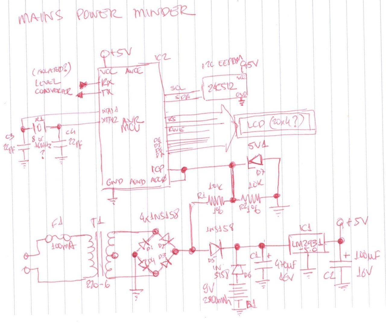
I briefly sketched a concept schematic, shown in the figure. It all starts with a
simple variation on the classic power supply: AC power goes to the transformer
(protected by a 100mA fuse), gets converted to 6VAC rms and is rectified by the
diode bridge. There it goes to ways -- to the signal conditioning unit and to
the voltage regulation unit. A battery connected provides backup power, with a
diode to prevent reverse current flows. The regulator unit is the classic LM2931
regulator with its two side capacitors, taken verbatim from its
datasheet. At the
end we have regulated 5VDC power for the digital circuits.
If we can keep the device's power consumption below 10mA, a set of ordinary AA
alkaline batteries, with their ~2800mAh capacity, might keep the device
alive for well over 280 hours in case of mains power loss. We could then
dispense with rechargeable batteries and their associated control circuitry.
The signal conditioning unit is just a resistor-based voltage divider to reduce
the 8.4Vpp (remember, to convert from VAC
rms
to volts peak-to-peak, you multiply
by the square root of two) from the transformer and halve it down to 4.2Vpp.
With two 10k resistors, current here won't be larger than 0.5mA, so we use a 5V1 zener
to protect us from transient overvoltages. The conditioned signal goes to the
MCU's ICP (input capture pin) for frequency measurement and to the ADC for voltage
measurement.
I think it's a good thing that the ADC is getting the "almost raw" alternating
current, because it gives us a lot of flexibility -- at the price of some complexity
in the software. For instance, the Vpp to Vrms conversion will have to be done in
software; to avoid
floating point,
we may need some integer arithmetic gymnastics.
To keep things simple, we'll communicate over serial.
We can always add a USB<->UART bridge later. We could do
software-USB,
but that would force our clock to be 12MHz and might present formidable timing constaints.
I don't want this complexity right now. Anyway, I haven't settled on an exact
RS-232
level converter just yet because I'm considering circuits using optocouplers to keep the signals electrically
isolated from the rest of the circuit as an additional safety precaution. What I do know is that I don't want a
MAX232,
because it takes a good 3mA and we're trying to be very low power.
We'd also have the classic LCD interface with E/RS/RW+D4..D7. Maybe we'll need
to provide a LCD shutdown line to conserve power when operating through the battery.
We need something for mass storage. We could have a SD card, but that would mean
a whole big set of burdens: at least 512 bytes of RAM for the write buffer (or
twice that if we need double buffering), which limits our MCU choices; and we'd
need a 3.3V rail as well, along with level converter for the data lines. For simplicity,
at this point I'm going with a standard
24C512
(64
kibibyte)
I2C EEPROM,
perhaps just because I happen to have one lying around here.
Next time I'll consider some of the basic calculations, clock and MCU selection, etc. See ya.
Follow-up posts: