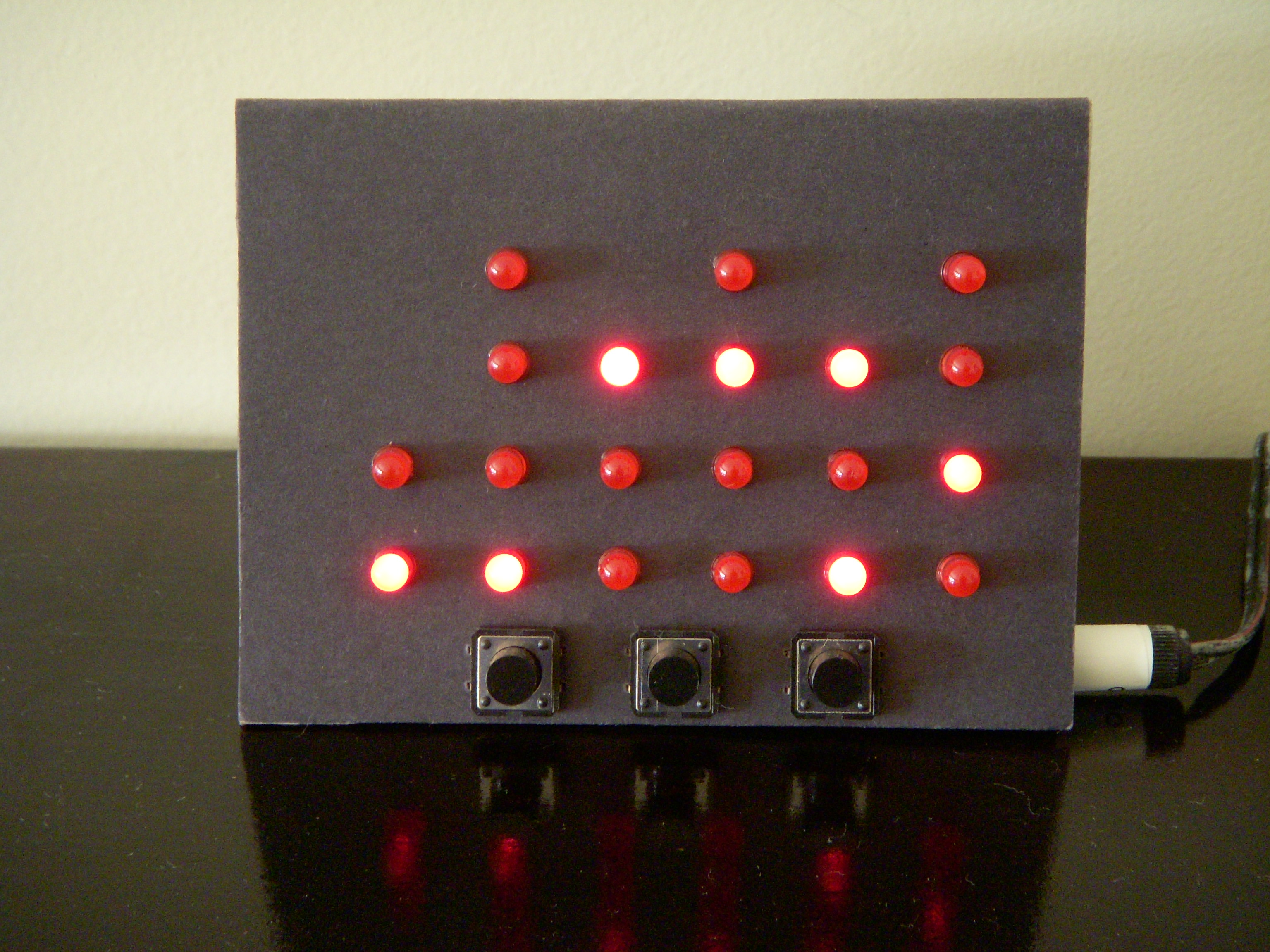
amatuerish but decent-looking cardboard case. You know the drill: click to enlarge. 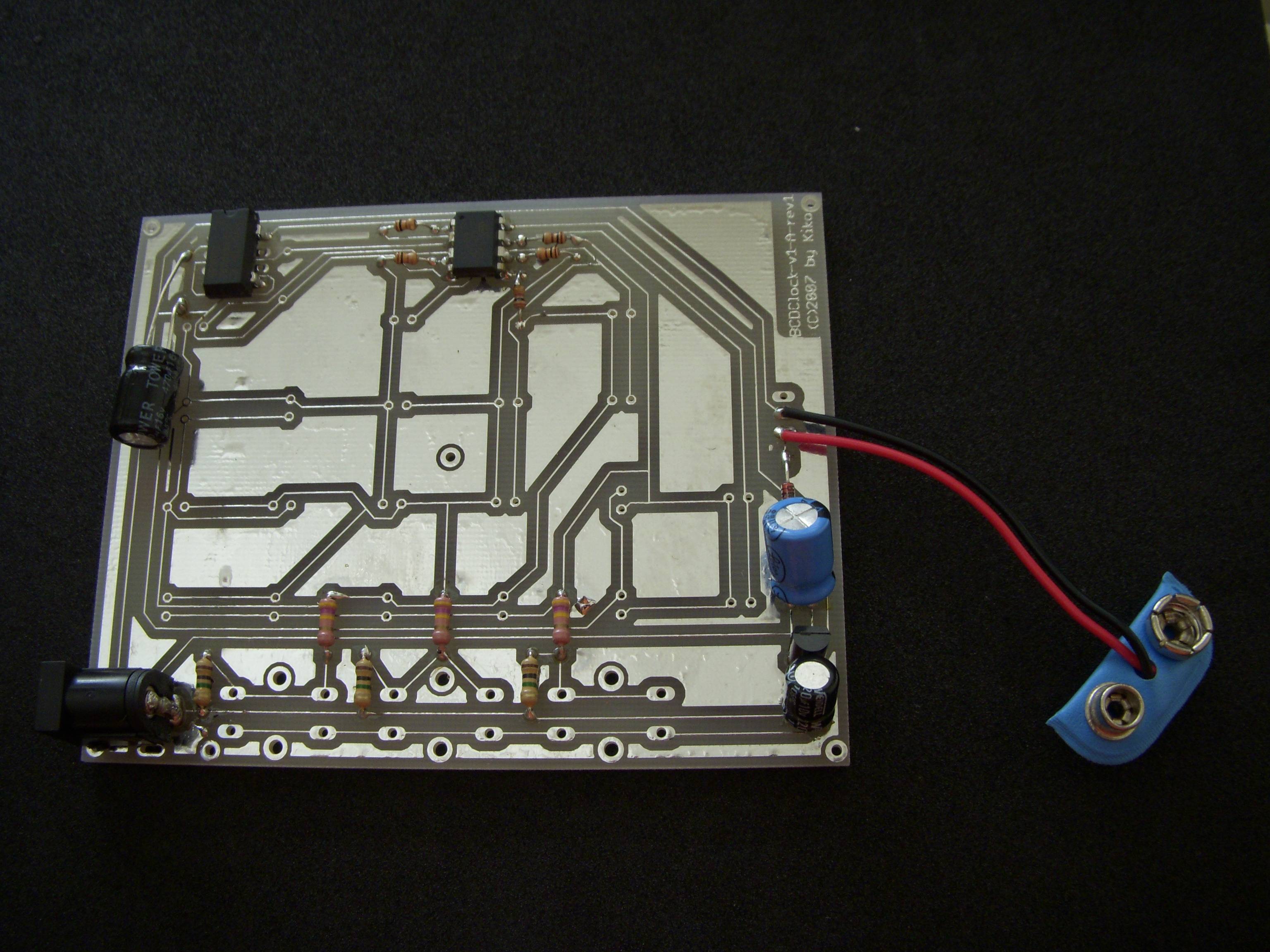
and buttons will be soldered facing the other side. Click to enlarge. 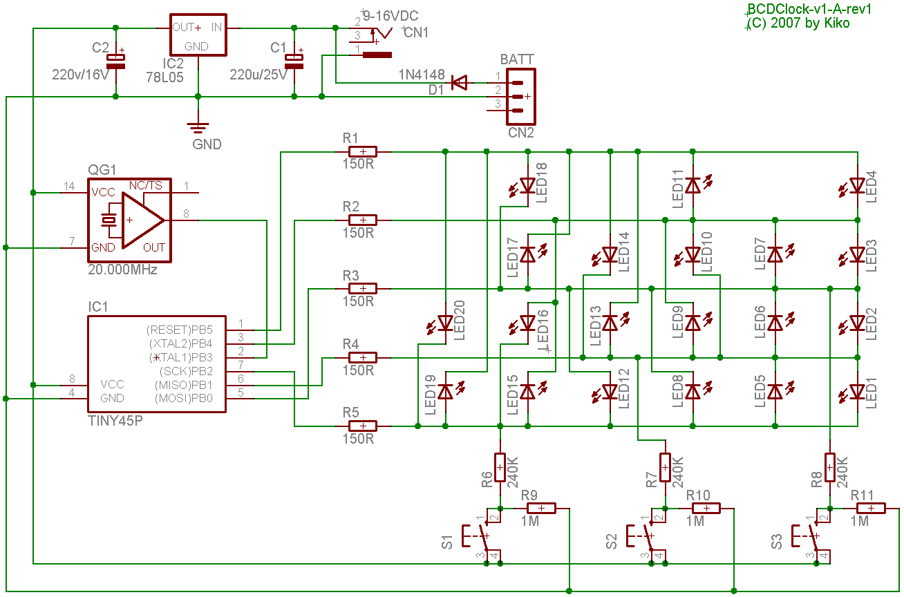
|
The Binary-Coded-Decimal ("Binary") Clock
A geekish clock using a single 8-pin AVR microcontroller that tells the time with LEDs in binary for each decimal digit, much like the famous ones from ThinkGeek, but with some exclusive features such as couting in Gray code.What is this binary clock thing anyway?
It's a digital clock that tells the time using binary digits instead of decimal digits. Binary clocks have become fashionably of late because of their retro "blinking lights" visual style reminiscent of 60's era mainframe computers which (despite some Hollywood exaggerations) did in fact have lots of blinking lights. Many adults like to think of it as geekishly convoluted way to display the time, but in fact pretty easy to read: in a conventional "hours and minutes hands" mechanical clock, you need to be able to add and multiply by five. In a binary clock, all you need to know is to add -- and in BCD mode, the addition gives at most 9. Sure, digital clocks with decimal displays are easier to read -- but that's a cultural thing: people are taught to think in decimal early in school. I know of some kids that learned to read the time in binary clocks before even learning the decimal system; one of them, years later, remarked to me that he finds analog clocks needlessly complicated, having been, back then, frustrated for being forced to learn to read it in school. This page teaches how to read binary clocks and how to build an inexpensive yet feature-rich one.But... why?
For sheer geekish fun. And just to look cool in my living room. Helps to keep my guests entertained. Some of them do shake their heads, aghast at my unapologetic geekiness. It's also quite useful to introduce binary notation to my students.Features
- Counts the time in two ways:
- Six digits for easiest reading; or
- Three groups of LEDs for hours, minutes and seconds for slightly more challenging reading;
- Displays the count either in either standard binary-coded-decimal notation or in binary-reflected Gray code for real elite reading skills
- Display mode can be dynamically changed with no need to restart
- Powered by a wall-wart 9V power supply
- Connector for optional 9V non-rechargeable battery backup: keeps time even in face of power failures
- Crystal oscillator for good accuracy and stability
- Low cost, less than $25 in parts. Much less if you don't use expensive high-intensity LEDs.
- Single-sided PCB, easy to make with amateur processes
Operation
This section explains how to operate the binary clock, assuming you have one already assembled and working. Many points here also apply to other binary clocks as well. If you want to learn how it works in depth or maybe assemble yours, see the Hardware section further on.Reading the Display
Each of the four display modes are described in their own pages:- The Classic BCD Mode, often but not very appropriately labeled as "the binary clock"
- The 3-Group Binary or "Hour-Minute-Second" mode, often but mistakenly labeled as "true binary clock"
- The Gray Code Variant of the Classic BCD Mode
- The Gray Code Variant of the 3-Group Mode
MODE (the rightmost key) while the clock is running, it will cycle among each of the modes above.
Adjusting the Time
There are three buttons, from left to right:HR, MIN and MODE.
Pressing either HR or MIN enters adjust mode, stopping the clock and zeroing the seconds counter. Pressing HR increments the hours counter; pressing MIN increments the minutes counter. They will wrap to zero after reaching their maximum values.
While in adjust mode, pressing MODE restarts the clock: the seconds counter will start counting again. The count starts when you release the MODE key. This makes it easy to manually synchronize with another clock within tenths of a second.
Hardware
Design
As usual, I tried the 'as simple and with as few components as possible' approach. I wanted see if the design could be made to fit an 8-pin MCU. Discounting the mandatoryVCC and GND pins, we have six usable I/O pins left.
The first important observation is that we can control 20 LEDs with only 5 pins. The animation below shows how: picture each control pin as a vertex of a K5 (the complete graph with 5 vertices, drawn below as a pentagon with all its diagnoals) where each edge (there are ten of them) has two diodes connected in antiparallel, totalling 20 LEDs. By sourcing current (outputting "1") at a specific pin and sinking at the other (outputting "0") while keeping the other three disconnected (i.e., as inputs), we can light one LED at a time.
Assembly and Installation tips
If you use the included single-sided PCB, pay attention to the following:- Most components are meant to be assembled in the copper side of the PCB; only the LEDs and the switches are to go to the other side.
- LED4's pins are very close to the metal can of the crystal oscillator. Don't let them touch.
- Mind the orientation/polarity of the LEDs.
- I suggest using a 12V power supply and the power plug negative must be the center pin, otherwise you'll instantaneously fry the circuit.
Firmware
Firmware Upload
I'm supposing you have already unpacked the distribution package in a directory of your choosing. The package comes with a precompiled images. WARNING: Since we use the/RESET pin as I/O, the uploading process will disable it. This means that if you don't have a high-voltage programmer such as Atmel's STK-500, you will be able to use the SPI-based In-System Programming only once.
Put the MCU in your favorite programming board. If you use avrdude and usbasp like I do, check that the paths and settings in the Makefile are OK for your system and type:
To set up the fuses, do:make upload_isp
Remember: from this point on, you will no longer be able to use SPI-based ISP. If you want to upgrade de firmware again using high-voltage programming, remove the chip and insert it into a high voltage programmer (such as avrdoper) and use:make fuses
Then put the chip back into the BCDClock board.make upload_hvsp
Building
Get yourself a recent avr-gcc (I used 3.4.4) with avr-libc 1.4.0 or higher. If you're under Windows, I guess recent WinAVR versions are fine, although GCC 4.x generates larger code under certain situations. Change the paths in theMakefile so they make sense in your system, then type make clean to get rid of the precompiled versions or any other cruft, then make. You should get the files main.hex and eeprom.hex as result.
Other Kinds of Software-based simulation
- Take a look at this Excel worksheet. It simulates several clocks, including a hour-and-minutes-only version of this one.
Porting to other chips
I've recently rewrote the software with the following guidelines:- Avoid any instructions that don't exist in the
avr1core (adiw,sbiw,lds,stdand the like); - Use only the Timer0 overflow interrupt instead of the compare match registers;
PB5 is open-drain output only (i.e., there is PINB5 and DDRB5 but no PORTB5, so it can be either high-impedance or pulling to ground). This means we can't use it to control all the 20 LEDs; we're limited to 16 LEDs.
The ATtiny11 is even worse: its PB5 (there's only PINB5 but no DDRB5 or PORTB5) can be used only as input, not output at all.
The ATTiny15 wouldn't work because of an entirely different reason: it doesn't accept an external clock.
It should be possible to use those chips, however, if we use PORTB4..0 for the LEDs and PINB5 to sample the 50/60Hz from the mains like many clocks do. This informative page shows that the utility companies in the Netherlands and around Europe condition the mains AC waveform to be very stable on the long run precisely so that clocks relying on them keep good time. I don't know if and how this is done here in Brazil. I plan to do some more research about that and maybe build new clocks using that technique and those "smaller" chips.
License and Downloads
- Download: bcdclock-1.0.tar.bz2 (1MB)
- Please see http://creativecommons.org/licenses/by-nc-sa/2.5/ for details.
Comparison to Similar Devices
- A similar clock by Hans Summers using several standard 74-series counters and logic chips. 6-digit BCD only, no Gray code, no battery backup.
- Another one along the same lines by Bill Bowden. It features 19 LEDs instead of 20, so it counts up to 12 hours.
- Another one by John Hall using the 3-group layout, using different colored LEDs. No Gray code, no battery backup.
- Electronic USA sells a binary clock kit for $49.95. Has battery backup, but it's 6-digit BCD only and no Gray code.
- I've already mentioned the one sold at ThinkGeek. The description page says it supports both 6-digit BCD and 3-group modes, but it seems to require a restart to change modes. No Gray code and says nothing about battery backup.
- Uses a single inexpensive chip;
- Less components, simpler to assemble;
- More flexible, since it's programmable; supports several modes as a result.
- Requires an AVR programmer to upload the firmware.
Ideas for future work
- Use different colored LEDs for different bit values. I don't know if that would make it more or less confusing... or if the result would be aesthetically pleasing.
- Using a chip with more pins (an AT90S1200 or ATtiny2313, perhaps) would allow us to do away with the oscillator and perhaps add a buzzer to make it a BCD alarm clock.
- As Knuth points out, there are many Gray code variants and several ways to count in binary; implementing some of them in the clock might be interesting.
Feedback
If you build such a device, please let me know! Same for comments, suggestions, criticisms, bugfixes, etc. Send them to: